Torque hinge mount
A bought friction hinge as a measured body, with its insert holes and the rule for which way it folds.
Adjustable torque hinges hold a lid at any angle. They are not symmetric: this one folds like a book with its countersunk sides together and stops the other way with the plain sides about 90 degrees apart. The module gives the hinge as a solid for fit checks, the heat-insert holes under each leaf, and the clearance its stiffness screw needs.
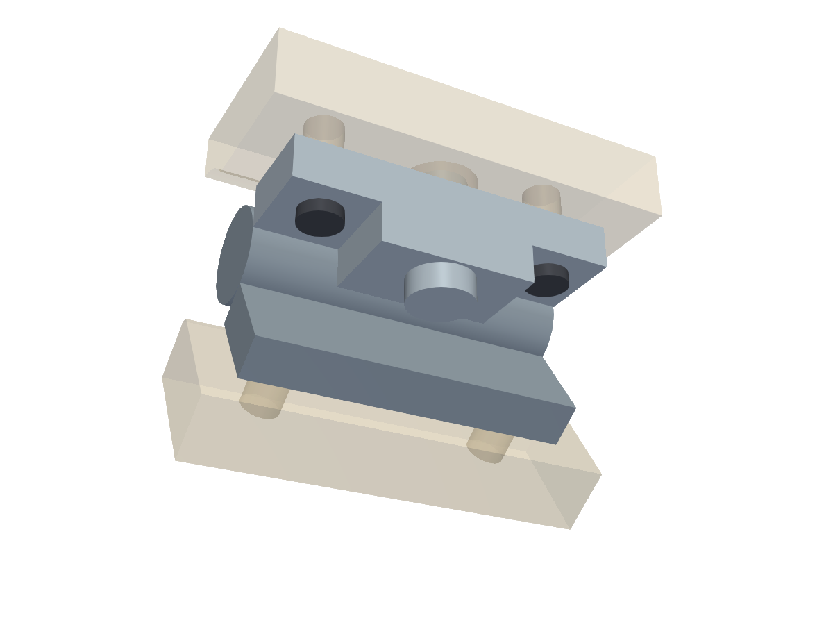 Loading 3D view
Use it in code
import { ready, hinge, checks, geom } from "partkit";
await ready();
const H = hinge.ANTRADER_E6;

lidPlatform = geom.cutAll(lidPlatform, hinge.movingLeafCuts(H));
const [fixed, moving] = hinge.bodies(H, 236);

const angles = Array.from({ length: 22 }, (_, i) => i * 5);   // 0 .. 105
const { worst, at } = checks.sweep((a) => [hinge.fixedSideAt(base, a), lid], angles);
if (worst > 0) throw new Error(`lid hits base at ${at} degrees`);
What you print
- Nothing by itself: it shapes the platforms in your lid and base
Hardware
- Adjustable torque hinge, E6 style, 0.79 N m (36.5 x 42.4 mm, 5.8 mm leaves)
- 4 x M3 heat-set inserts (5 mm OD, 6 mm long) per hinge
- 4 x M3 x 8 button-head screws per hinge
Functions
| Call | What it gives you |
|---|---|
| hinge.ANTRADER_E6 | The measured hinge. |
| hinge.bodies(h, fixedDeg) | [fixed half, moving half] as solids for checks. |
| hinge.movingLeafCuts(h) / hinge.fixedLeafCuts(h, deg) | Insert holes under each leaf, plus a relief for the stiffness screw's nut. |
| hinge.fixedSideAt(part, openDeg) | The base side as seen from the lid at a given opening angle, for sweeps. |
Frame. The hinge axis is X through the origin. The moving leaf (the one with the stiffness screw; put it on the lid) lies along -y with its plain face at z = +barR. The fixed leaf points in direction fixedDeg in the YZ plane.
Sizes
Millimetres. These defaults are the sizes that were printed; other values are untested.
| Name | Default | Meaning |
|---|---|---|
| name | Antrader E6-style adjustable torque hinge, 0.79 N m | What it is |
| length | 42.44 | Along the barrel |
| across | 36.48 | Over both leaves, laid flat |
| leafT | 5.77 | Leaf thickness |
| barR | 6.25 | Barrel radius |
| holesAlong | 31.04 | Mounting-hole spacing along the barrel |
| holesAcross | 26.06 | Mounting-hole spacing across the barrel |
| blockW | 20.33 | Width of the raised block round the stiffness screw |
| blockH | 5.17 | Height of that block above the countersunk face |
| screwY | 13.5 | Stiffness screw centre from the axis |
| screwHeadD | 8.6 | Stiffness screw head diameter |
| screwTop | 8.48 | Top of that screw above the countersunk face |
| nutR | 3.5 | Its nut's radius |
| nutH | 2.4 | How far the nut can show on the plain face |
| closedMinDeg | 27 | Smallest angle between the leaves |
| clearR | 9.5 | Keep printed parts this far from the axis |
Check before you print
- Lid against base at every 5 degrees from closed to fully open
- Keep printed parts 9.5 mm from the axis round the barrel
- The stiffness screw must stay reachable, or be set before the hinge goes in
Learned the hard way
- Fold a bought hinge both ways by hand and write down where it stops before designing round it.
- Measure everything that sticks out, on both faces: the stiffness screw, its raised block, its nut.
Open it in Fusion 360
The scene above as a STEP file: real solid bodies, each part its own named component, in position. In Fusion 360 use File, Open, then Open from my computer. It also opens in FreeCAD, SolidWorks and Onshape. It carries the shapes, not the sizes you can change; for different sizes, use Make it above or change them in code.
Source: ts/src/hinge.ts
/** Bought torque (friction) hinges and how to mount them.
 *  THE RULE THAT COST TWO REPRINTS: this hinge folds like a book with the COUNTERSUNK sides (the side with the big
 *  stiffness screw) toward each other, down to about 27 degrees; the other way it stops with the plain sides about
 *  90 degrees apart. Fold any bought hinge both ways by hand and write down where it stops before designing round it.
 *  Frame: the axis is X through the origin. The MOVING leaf (with the stiffness screw; put it on the lid) lies along -y
 *  with its plain face at z = +barR. The FIXED leaf points in direction fixedDeg in the YZ plane. */
import { box, xcyl, zcyl, framePrism, type Solid } from "./geom";
import { M3_INSERT_D } from "./fasteners";

export interface TorqueHinge {
  name: string; length: number; across: number; leafT: number; barR: number; holesAlong: number; holesAcross: number;
  blockW: number; blockH: number; screwY: number; screwHeadD: number; screwTop: number; nutR: number; nutH: number;
  closedMinDeg: number; clearR: number;
}

export const ANTRADER_E6: TorqueHinge = {
  name: "Antrader E6-style adjustable torque hinge, 0.79 N m",
  length: 42.44, across: 36.48, leafT: 5.77, barR: 6.25, holesAlong: 31.04, holesAcross: 26.06,
  blockW: 20.33, blockH: 10.94 - 5.77, screwY: 13.5, screwHeadD: 8.6, screwTop: 14.25 - 5.77,
  nutR: 3.5, nutH: 2.4, closedMinDeg: 27, clearR: 9.5,
};

const face = (h: TorqueHinge) => h.barR - h.leafT;

/** [fixed half, moving half] as solids for previews and fit checks. */
export function bodies(h: TorqueHinge = ANTRADER_E6, fixedDeg = 236): [Solid, Solid] {
  const x0 = -h.length / 2, x1 = h.length / 2, half = h.across / 2, f = face(h);
  const fixed = xcyl(h.barR, x0, x1).fuse(framePrism(fixedDeg, 6.3, half, f, h.barR, x0, x1));
  const moving = box(x0, x1, -half, -6.3, f, h.barR)
    .fuse(box(-h.blockW / 2, h.blockW / 2, -half, -6.3, f - h.blockH, f + 0.01))
    .fuse(zcyl(h.screwHeadD / 2, 0, -h.screwY, f - h.screwTop, f))
    .fuse(zcyl(h.nutR, 0, -h.screwY, h.barR - 0.01, h.barR + h.nutH));
  return [fixed, moving];
}

/** Cut from the platform on the moving leaf's plain face: two insert holes and a relief for the stiffness screw's nut. */
export function movingLeafCuts(h: TorqueHinge = ANTRADER_E6, insertDepth = 6.2): Solid[] {
  const tools = [-h.holesAlong / 2, h.holesAlong / 2].map((dx) => zcyl(M3_INSERT_D / 2, dx, -h.holesAcross / 2, h.barR - 0.1, h.barR + insertDepth));
  tools.push(zcyl(h.nutR + 1.3, 0, -h.screwY, h.barR - 0.1, h.barR + h.nutH + 0.4));
  return tools;
}

/** Cut from the platform behind the fixed leaf's plain face: two insert holes. */
export function fixedLeafCuts(h: TorqueHinge = ANTRADER_E6, fixedDeg = 236, insertDepth = 6.2): Solid[] {
  const r = (fixedDeg * Math.PI) / 180, d = [Math.cos(r), Math.sin(r)], n = [-d[1], d[0]], a = h.holesAcross / 2;
  return [-h.holesAlong / 2, h.holesAlong / 2].map((dx) =>
    zcyl(M3_INSERT_D / 2, 0, 0, -0.2, insertDepth)
      .rotate(fixedDeg, [0, 0, 0], [1, 0, 0])
      .translate(dx, a * d[0] + h.barR * n[0], a * d[1] + h.barR * n[1]) as Solid,
  );
}

/** Button heads of the moving leaf's two mounting screws. */
export function mountingScrewHeads(h: TorqueHinge = ANTRADER_E6, headD = 5.7, headH = 1.65): Solid {
  const f = face(h);
  const [a, b] = [-h.holesAlong / 2, h.holesAlong / 2].map((dx) => zcyl(headD / 2, dx, -h.holesAcross / 2, f - headH, f));
  return a.fuse(b);
}

/** A part of the FIXED side, seen from the lid's frame with the lid opened by openDeg. */
export const fixedSideAt = (part: Solid, openDeg: number): Solid => part.clone().rotate(openDeg, [0, 0, 0], [1, 0, 0]) as Solid;